- Using SafetyCulture
- Sensors
- Turn on, off, and reset sensors and gateways
Turn on, off, and reset sensors and gateways
Learn how to turn on, off, and reset your sensors and gateways prior to adding them to SafetyCulture.What are sensors?
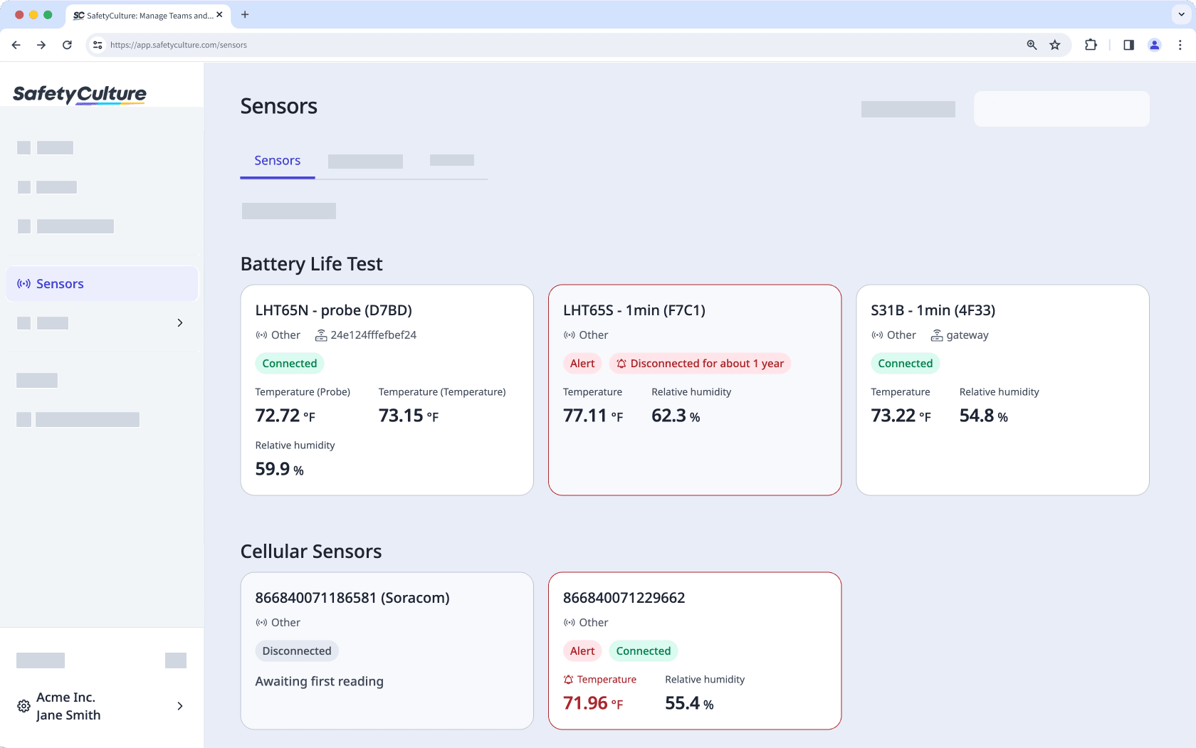
Sensors in SafetyCulture automatically track conditions like temperature in the places that matter most to your operations. Instead of relying only on manual checks or paper logs, sensors send frequent readings into SafetyCulture so you can spot trends, respond early to problems, and keep a clear digital record for audits. With alerts in place, the right people can be notified when readings move outside the range you set, helping protect stock, equipment, and compliance.
Each sensor sends its readings to a nearby gateway, which then sends that data to SafetyCulture. Gateways act as the bridge between your sensors and your account, collecting data from any sensors within range. This empowers you to stay compliant, prevent asset loss, and make informed decisions based on historical sensor data trends.
If you're an existing sensors customer interested in purchasing additional gateways and sensors, please reach out to your dedicated customer success manager. Otherwise, get in touch if you're:
Interested in purchasing sensors and gateways from us.
Considering purchasing sensors and gateways from third parties.
Interested in finding out more about our sensor solutions.
We recommend that you set aside 10 to 15 minutes to complete the self-installation. Make sure you follow each step carefully, and if you get stuck at any time, review the troubleshooting tips at the end of this article.
Sensors upload a reading every 10 minutes and you will receive readings until the device is offline. For the sensor to register as offline in the app, the device must be offline for 60 minutes.
Turn on, off, and reset sensors
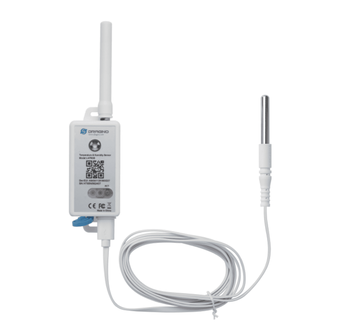
Turn on
Press and hold the ACT button on the front of the device for at least five seconds. If you're using an older device, the ACT button is at the bottom. You can use a pen or something similar to press the button more firmly.
A green light should flash five times, followed by a red light.
If a gateway is within range, another green light should flash briefly, indicating that a reading is sent and received successfully.
Turn off
Press the ACT button on the front of the device five times in a row. If you're using an older device, the ACT button is at the bottom.
A red light should display briefly, indicating that the device is off.
Reset
Press and hold the ACT button on the front of the device for at least five seconds. If you're using an older device, the ACT button is at the bottom.
A green light should flash five times, followed by a red light.
If a gateway is within range, another green light should flash briefly, indicating that a reading is sent and received successfully.
Send a reading manually
Press and hold the ACT button on the front of the device for three seconds.
A red light should flash, indicating that you sent a reading manually. If you have an external probe attached to your device, a blue light should flash instead. You can send a reading manually for this device once every ten minutes.
This device has two variations. If you use an older version, there is no ACT button, and you will need a Phillips screwdriver. Thus, the processes may differ between these versions.
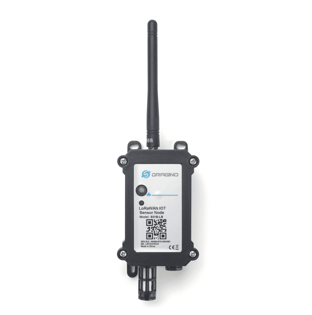
Turn on
Press and hold the ACT button on the front of the device.
The LED should flash green five times, followed by a blue light.
If a gateway is within range, a green light should flash briefly, indicating that a reading is sent and received successfully.
Turn off
Press the ACT button on the front of the device five times in a row.
A red light should display briefly, indicating that the device is off.
Reset
Press and hold the ACT button on the front of the device.
The LED should flash green five times, followed by a blue light.
If a gateway is within range, a green light should flash briefly, indicating that a reading is sent and received successfully.
Send a reading manually
Press and hold the ACT button on the front of the device for three seconds.
A blue light should flash, indicating you sent a reading manually. You can send a reading manually for this device once every ten minutes.
This device has two variations. If you use an older version, there is no ACT button, and you will need a Phillips screwdriver. Thus, the processes may differ between these versions.
Turn on
Using a Phillips screwdriver, remove the four screws on the front of the device.
Remove the lid.
Remove the yellow jumper from the pin.
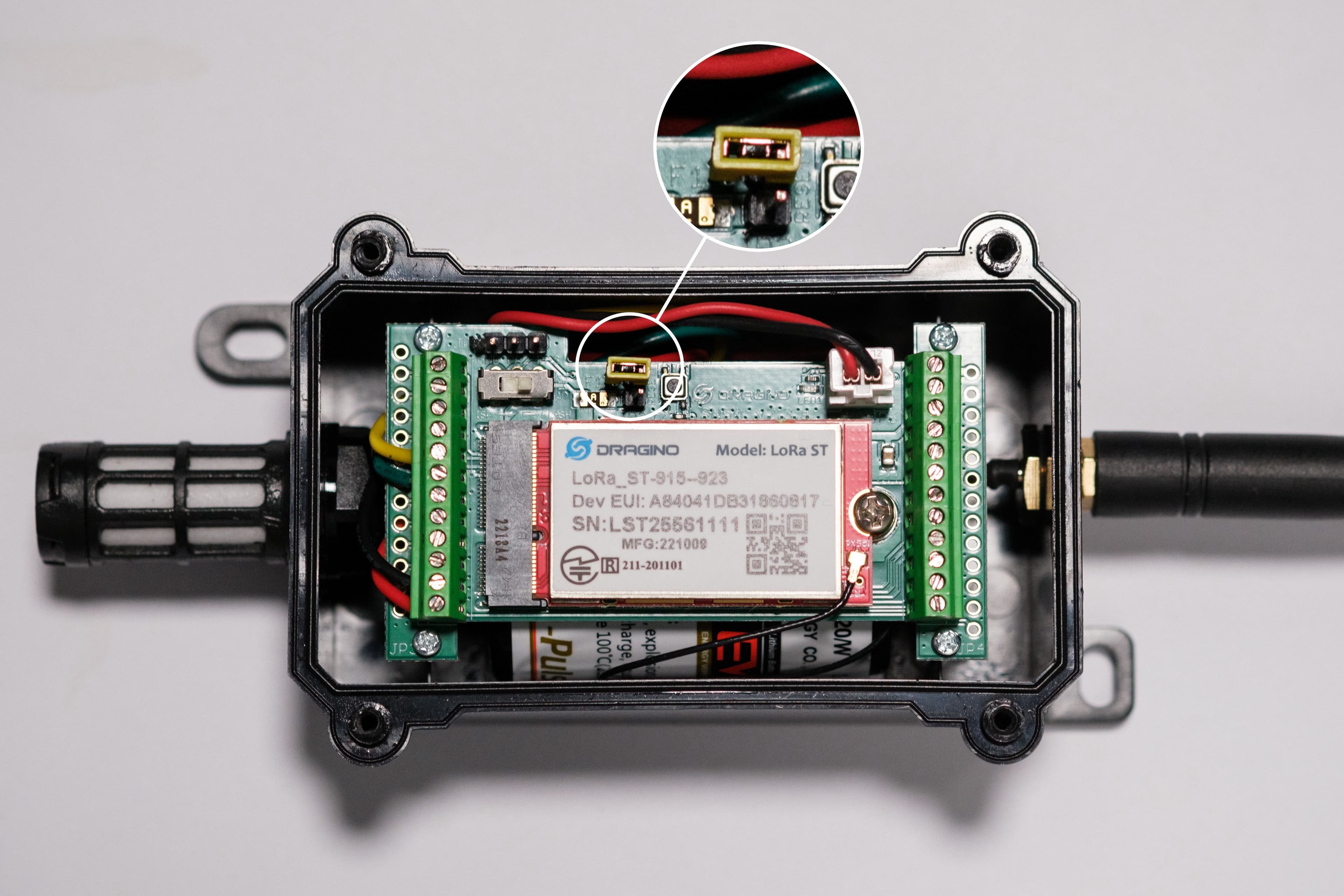
Place the yellow jumper over both pins vertically. The LED on the motherboard should flash green.
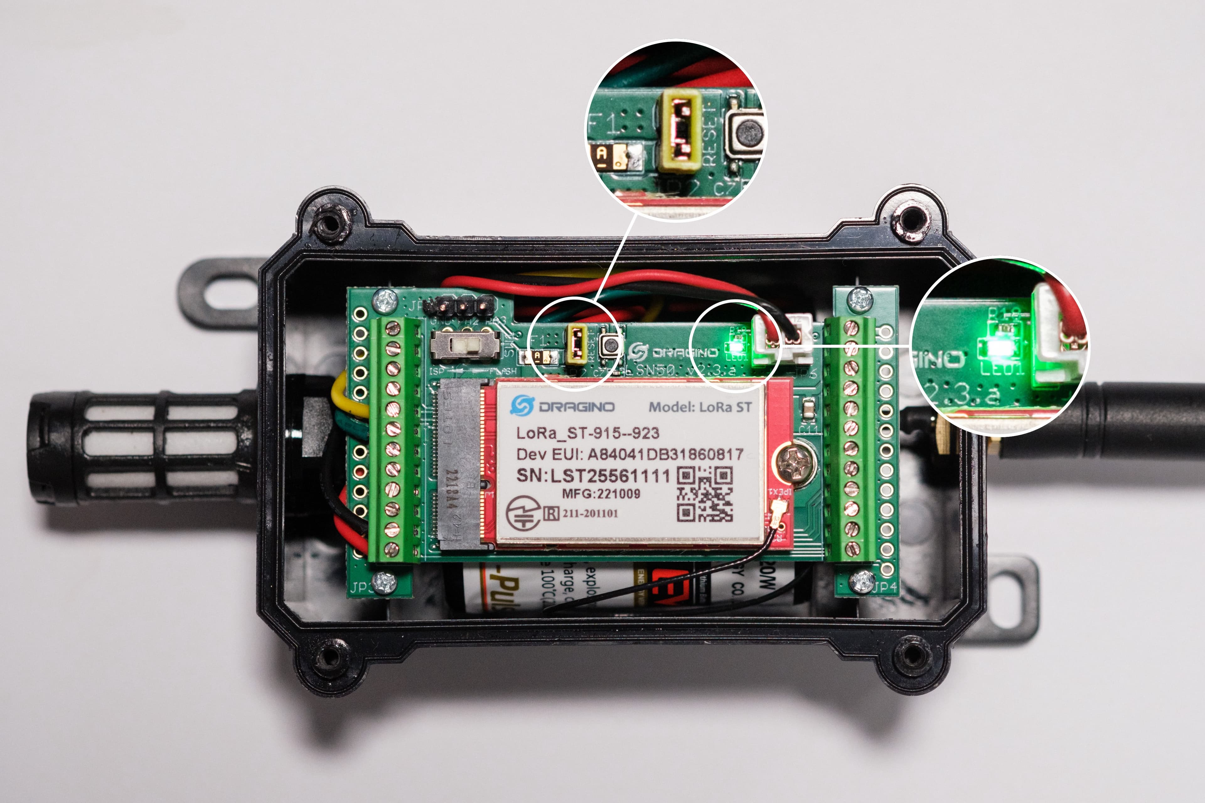
Place the lid back on the device.
Using a Phillips screwdriver, secure the four screws on the front of the device. Ensure these are fastened, and the device is watertight.
Turn off
Using a Phillips screwdriver, remove the four screws on the front of the device.
Remove the lid.
Remove the yellow jumper from the two pins.
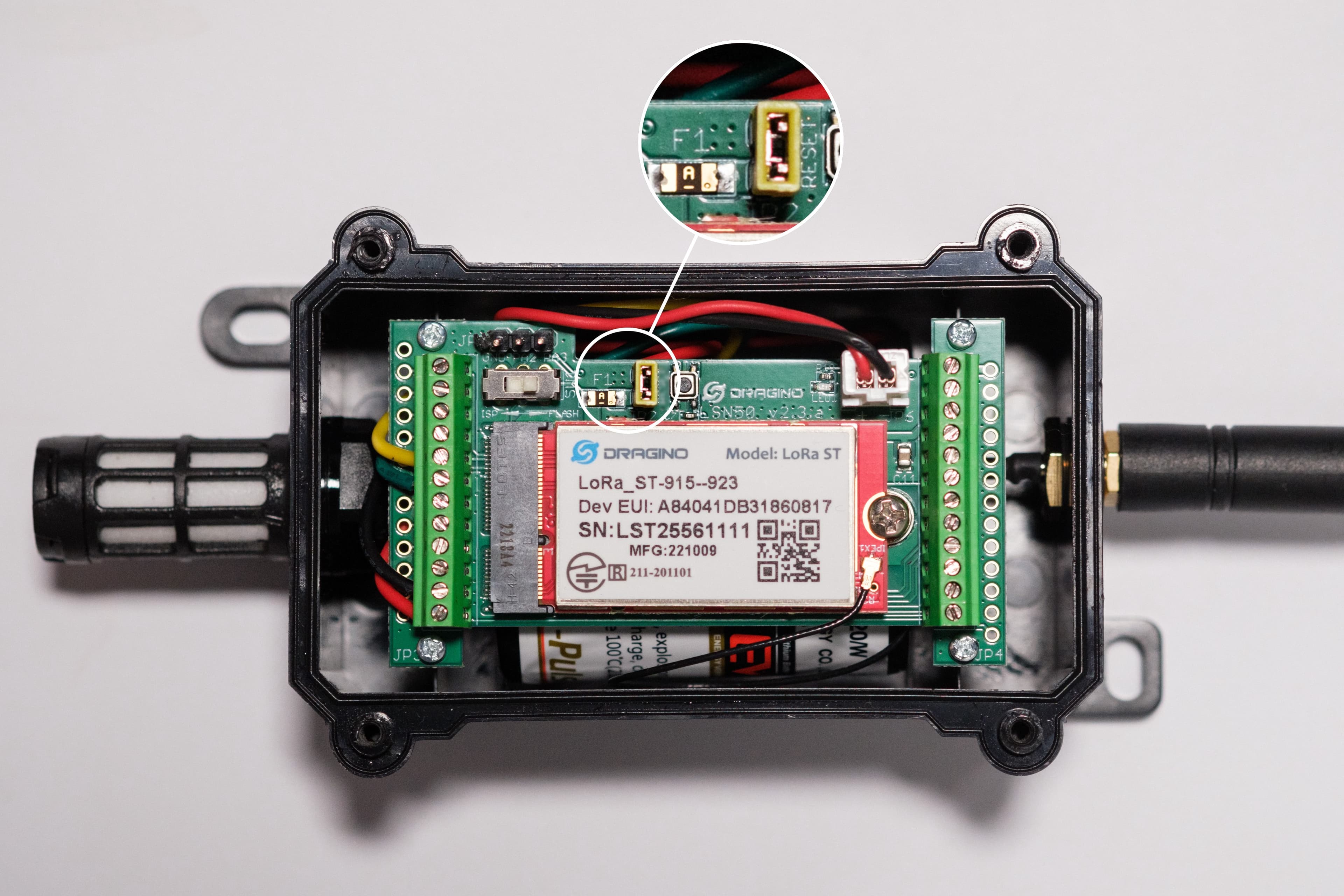
Place the yellow jumper over one of the pins horizontally.

Place the lid back on the device.
Using a Phillips screwdriver, secure the four screws on the front of the device. Ensure these are fastened, and the device is watertight.
Reset
Using a Phillips screwdriver, remove the four screws on the front of the device.
Remove the lid.
Press the reset button. The LED on the motherboard should flash green.
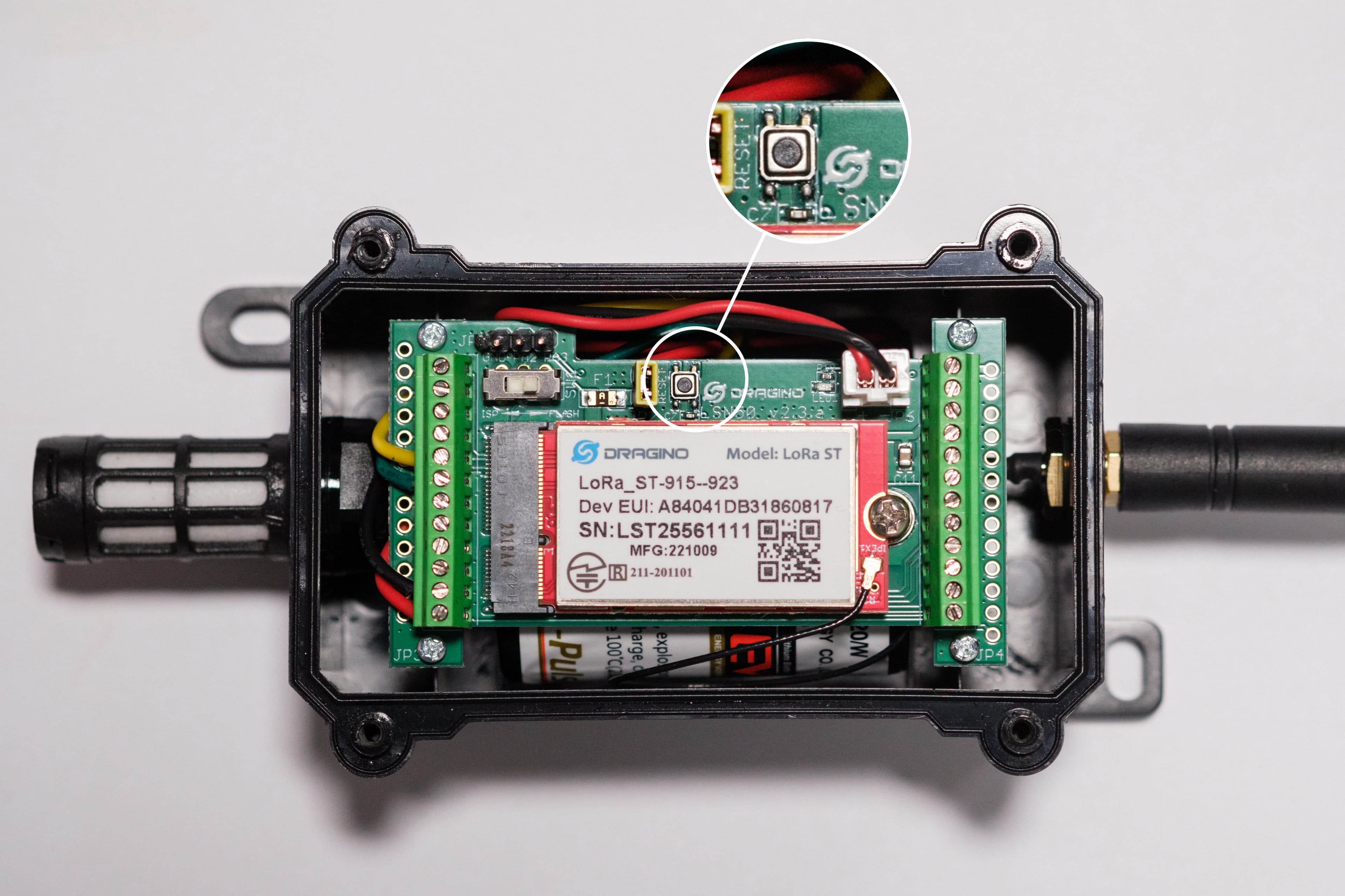
Place the lid back on the device.
Using a Phillips screwdriver, secure the four screws on the front of the device. Ensure these are fastened, and the device is watertight.
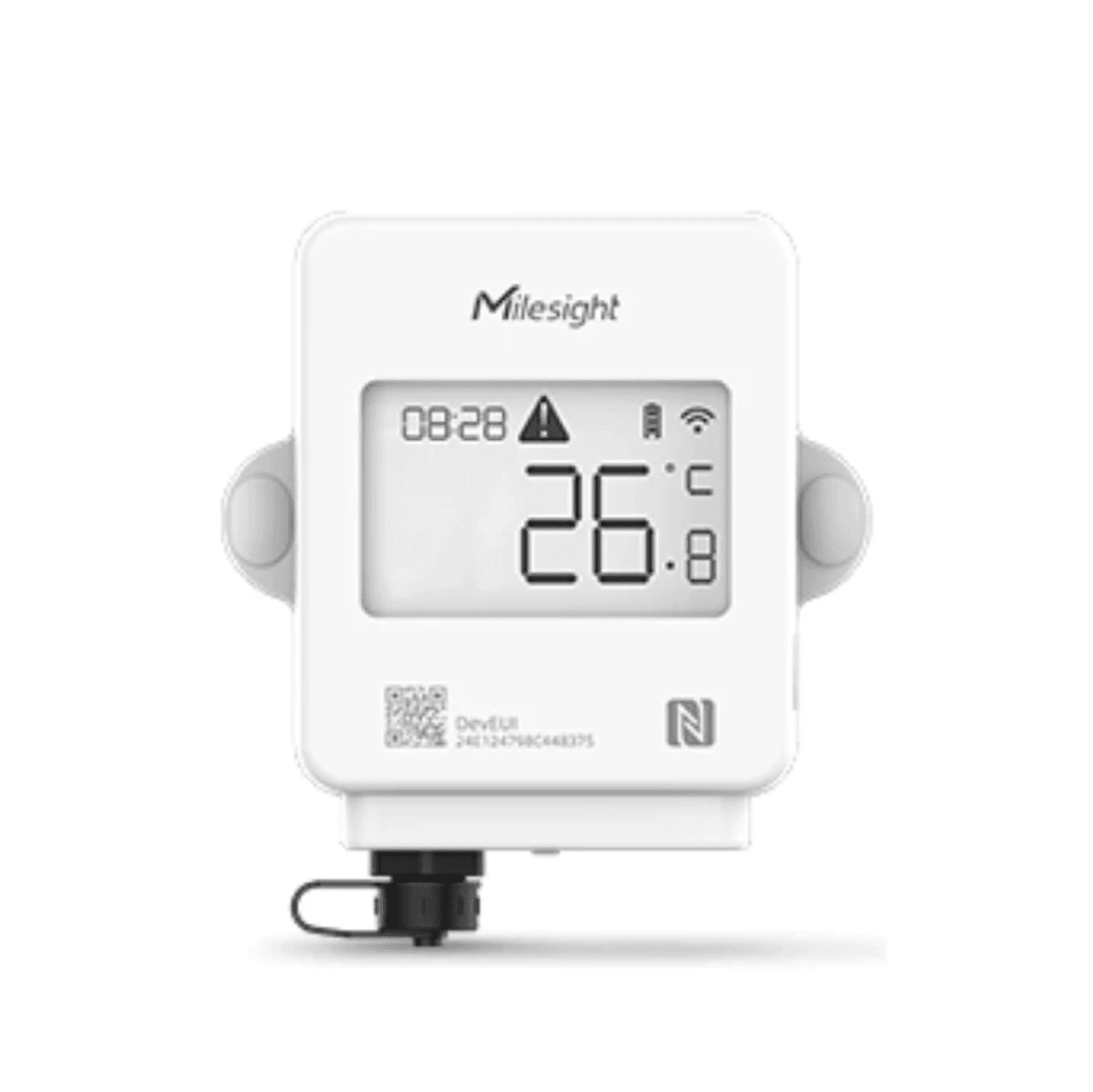
Turn on
Connect the probe to the bottom of the device.
Press and hold the power button on the right-hand side of the device for more than three seconds.
Icons are displayed on the screen for three seconds. If you turn the device on before connecting the probe, the screen appears blank until it is connected.
Turn off
Use a Phillips screwdriver to remove the four screws on the back of the device.
Remove the back cover and the batteries.
Re-attach the back cover.
Use a Phillips screwdriver to secure the four screws on the back of the device.
Reset
Use a Phillips screwdriver to remove the four screws on the back of the device.
Press and hold the reset button for 10 seconds.
A green light displays.
When the light disappears, continue to hold the reset button for another ten seconds.
The screen turns off.
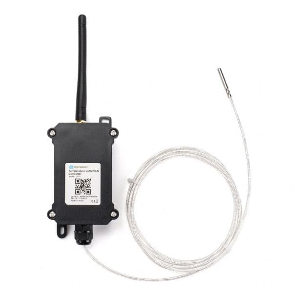
Turn on
Using a Phillips screwdriver, remove the four screws on the front of the device.
Remove the lid.
Remove the yellow jumper from the pin.

Place the yellow jumper over both pins vertically.

Place the lid back on the device.
Using a Phillips screwdriver, secure the four screws on the front of the device. Ensure these are fastened, and the device is watertight.
Turn off
Using a Phillips screwdriver, remove the four screws on the front of the device.
Remove the lid.
Remove the yellow jumper from the two pins.

Place the yellow jumper over one of the pins horizontally.

Place the lid back on the device.
Using a Phillips screwdriver, secure the four screws on the front of the device. Ensure these are fastened, and the device is watertight.
Reset
Using a Phillips screwdriver, remove the four screws on the front of the device.
Remove the lid.
Press the reset button. The LED on the circuit board should flash.

Place the lid back on the device.
Using a Phillips screwdriver, secure the four screws on the front of the device. Ensure these are fastened, and the device is watertight.
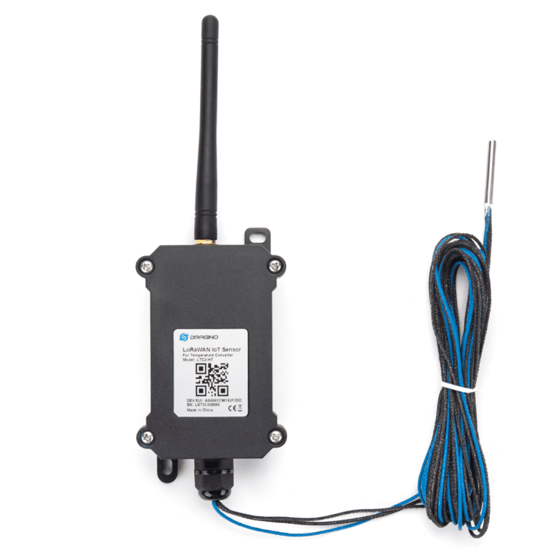
Turn on
Using a Phillips screwdriver, remove the four screws on the front of the device.
Remove the lid.
Remove the yellow jumper from the pin.

Place the yellow jumper over both pins vertically.

Place the lid back on the device.
Using a Phillips screwdriver, secure the four screws on the front of the device. Ensure these are fastened, and the device is watertight.
Turn off
Using a Phillips screwdriver, remove the four screws on the front of the device.
Remove the lid.
Remove the yellow jumper from the two pins.

Place the yellow jumper over one of the pins horizontally.

Place the lid back on the device.
Using a Phillips screwdriver, secure the four screws on the front of the device. Ensure these are fastened, and the device is watertight.
Reset
Using a Phillips screwdriver, remove the four screws on the front of the device.
Remove the lid.
Press the reset button. The LED on the circuit board flashes.

Place the lid back on the device.
Using a Phillips screwdriver, secure the four screws on the front of the device. Ensure these are fastened, and the device is watertight.
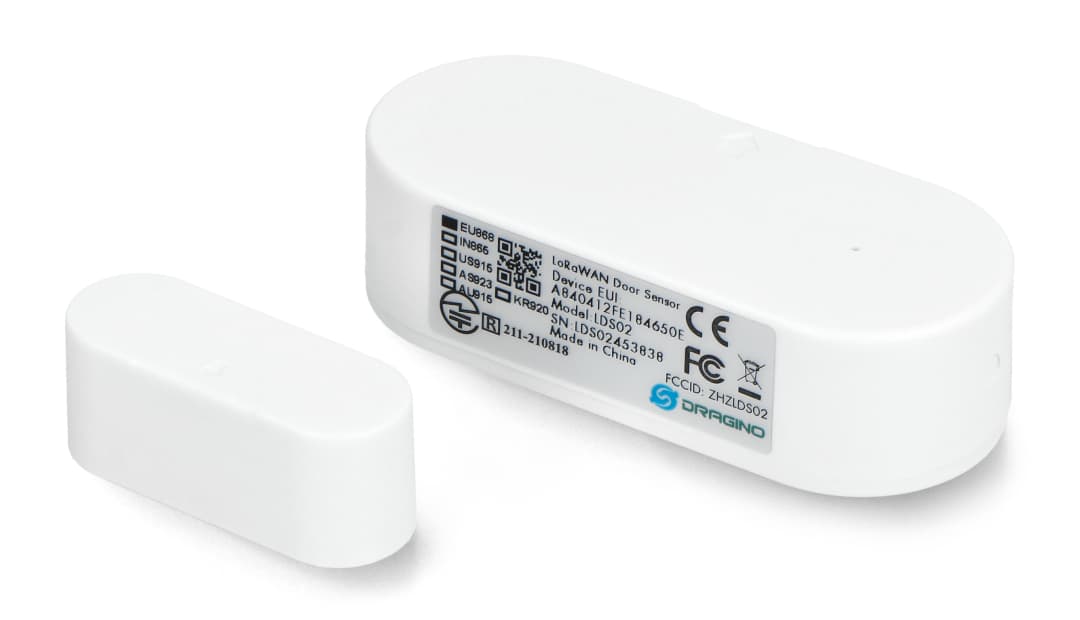
Turn on
Slide the battery cover off the back of the device.
Insert two standard AAA batteries. The sensor automatically turns on.
Slide the battery cover back on the device.
Turn off
Slide the battery cover off the back of the device.
Remove the standard AAA batteries. The sensor automatically turns off.
Slide the battery cover back on the device.
Reset
Slide the battery cover off the back of the device.
Remove the standard AAA batteries. The sensor resets.
Slide the battery cover back on the device.
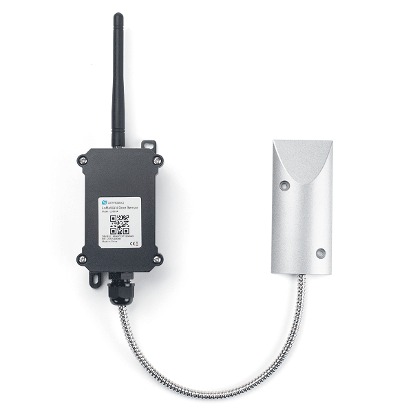
Turn on
Use a Phillips screwdriver to remove the four screws on the front of the device.
Remove the lid.
Remove the yellow jumper from the pin.
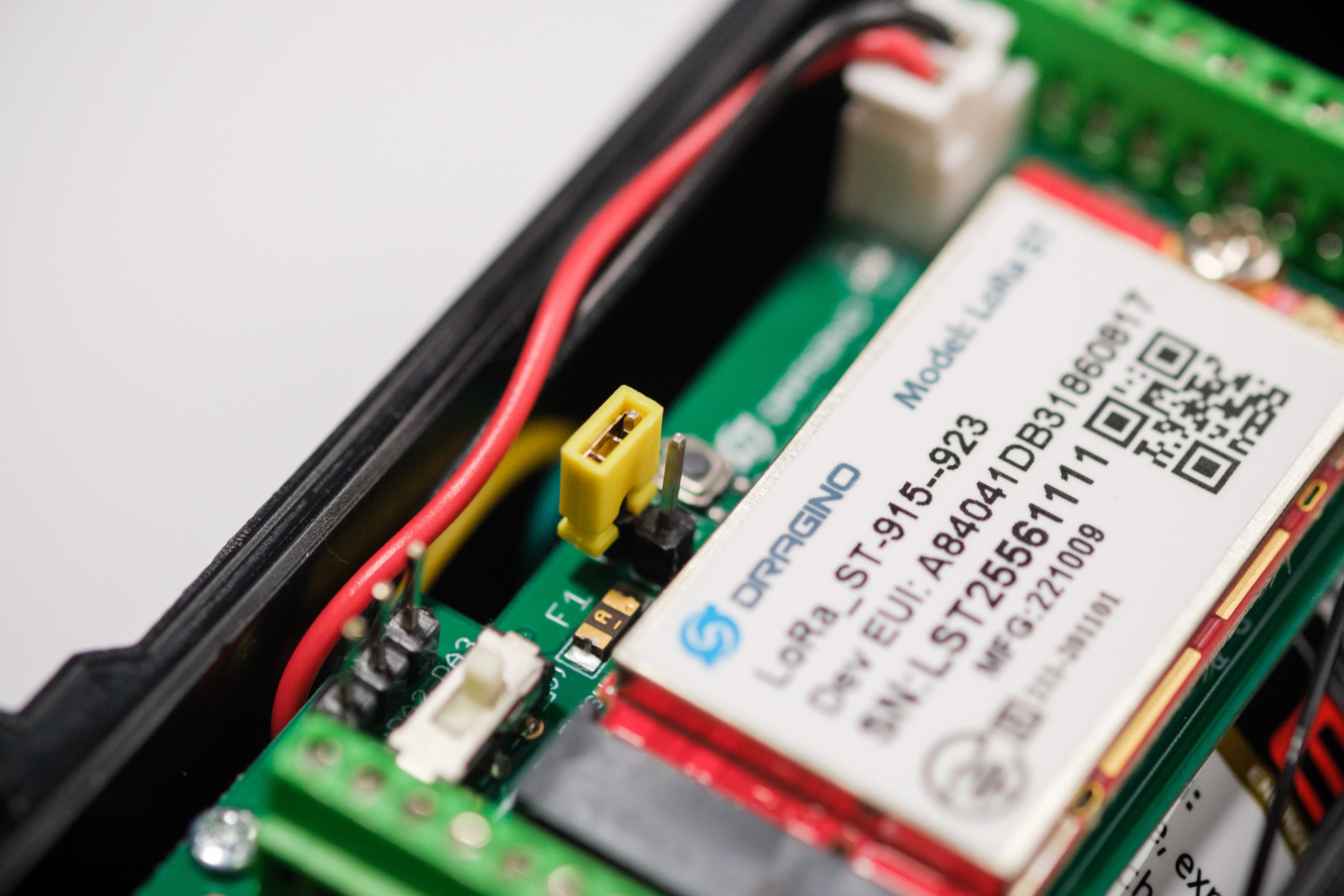
Place the yellow jumper over both pins vertically.
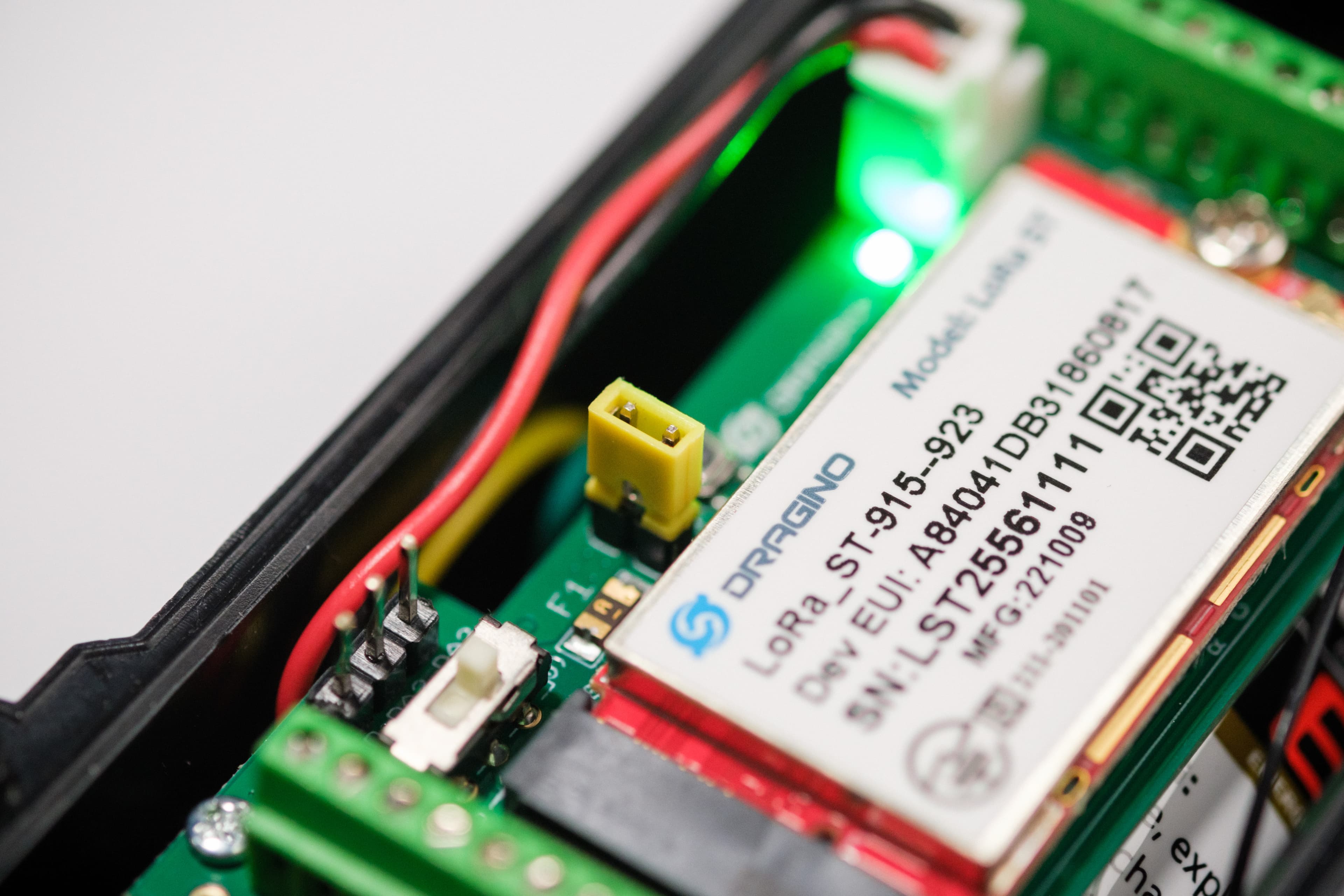
Place the lid back on the device.
Use a Phillips screwdriver to secure the four screws on the front of the device.
Turn off
Use a Phillips screwdriver to remove the four screws on the front of the device.
Remove the lid.
Remove the yellow jumper from the two pins.

Place the yellow jumper over one of the pins horizontally.

Place the lid back on the device.
Use a Phillips screwdriver to secure the four screws on the front of the device.
Reset
Use a Phillips screwdriver to remove the four screws on the front of the device.
Remove the lid.
Press the reset button. A light should flash briefly.
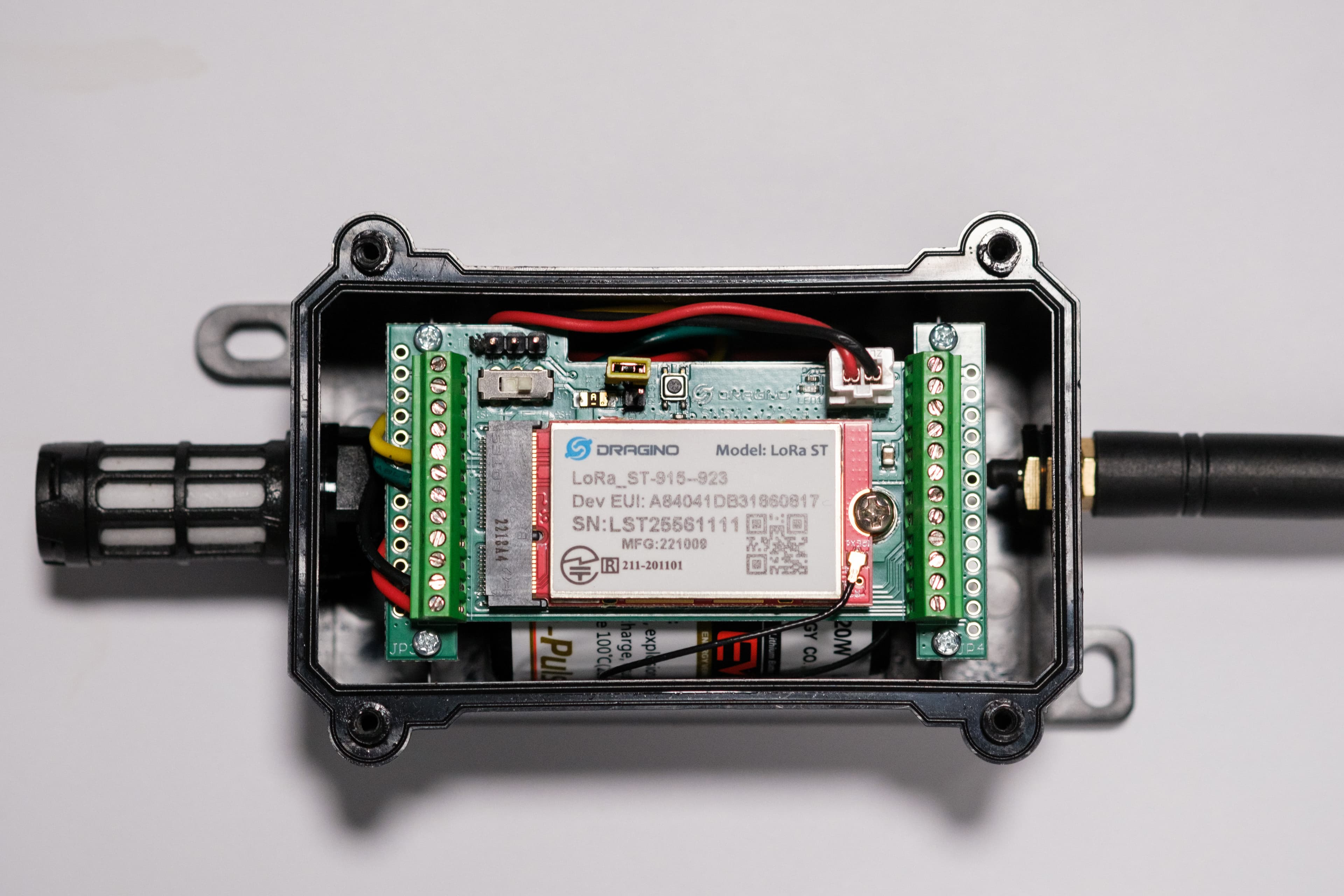
Place the lid back on the device.
Use a Phillips screwdriver to secure the four screws on the front of the device.
Turn on
Remove the cover at the back of the device.
Insert the two batteries included in the package.
Place the cover at the back of the device.
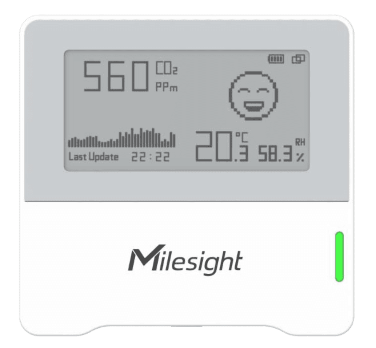
Press and hold the power button on the top of the device for three seconds or longer. The E-ink screen should flash, indicating that the device is on.
Turn off
1. Press and hold the power button on the top of the device for three seconds or longer.
Reset
Press and hold the power button for more than 10 seconds. The device resets to its default factory settings.
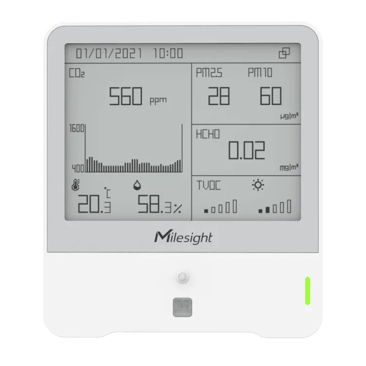
Turn on
Using a Phillips screwdriver, remove the screw from the back cover.
Connect the cable included in the package to the power adapter.
Connect the device to a power source.
Place the cover back on the device.
Using a Phillips screwdriver, secure the screw on the back cover.
Plug in the device.
Press and hold the power button for three seconds or longer. The E-ink screen should flash, indicating that the device is on.
Turn off
1. Press and hold the power button for three seconds or longer.
Reset
Press and hold the power button for more than 10 seconds. The device resets to its default factory settings.
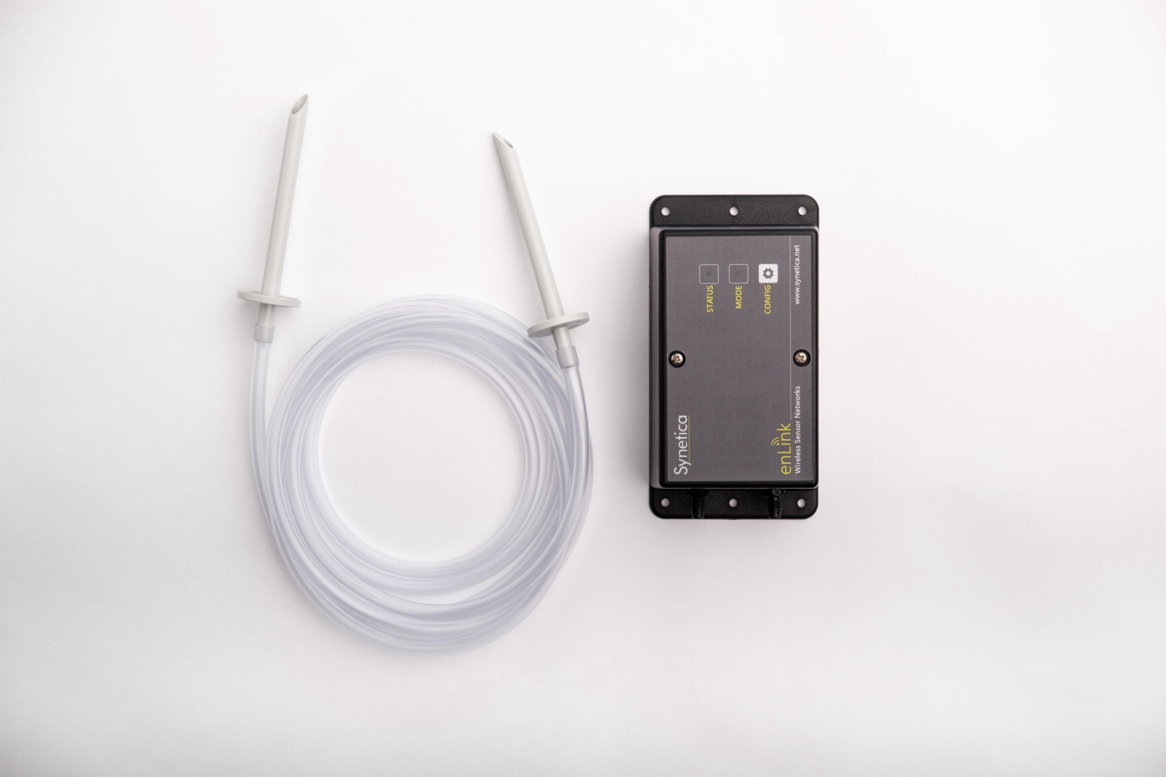
Turn on
Use a Phillips screwdriver to remove the two screws on the front of the device.
Remove the cover.
Insert two x AA batteries.
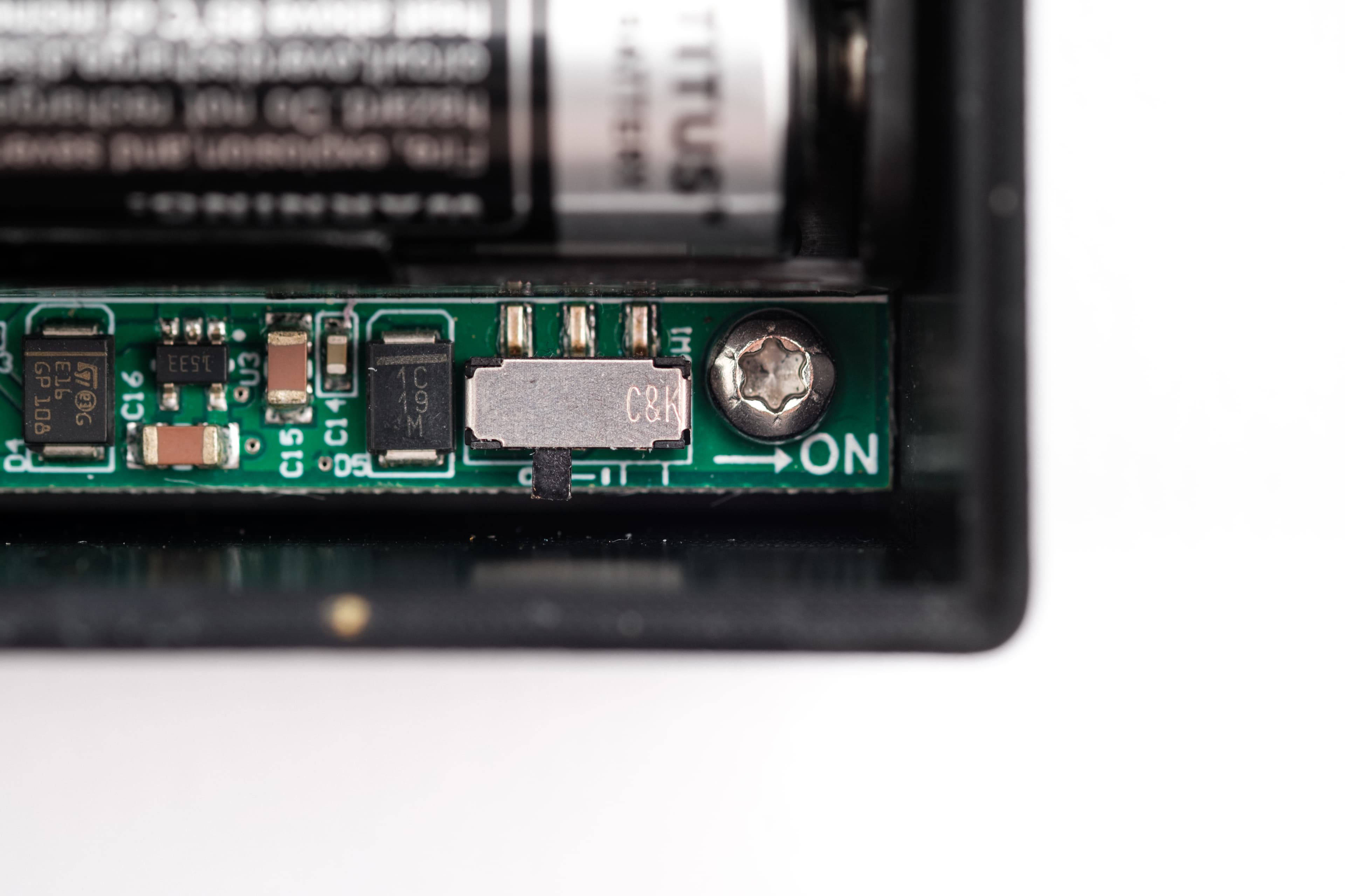
Move the ON switch to the right.
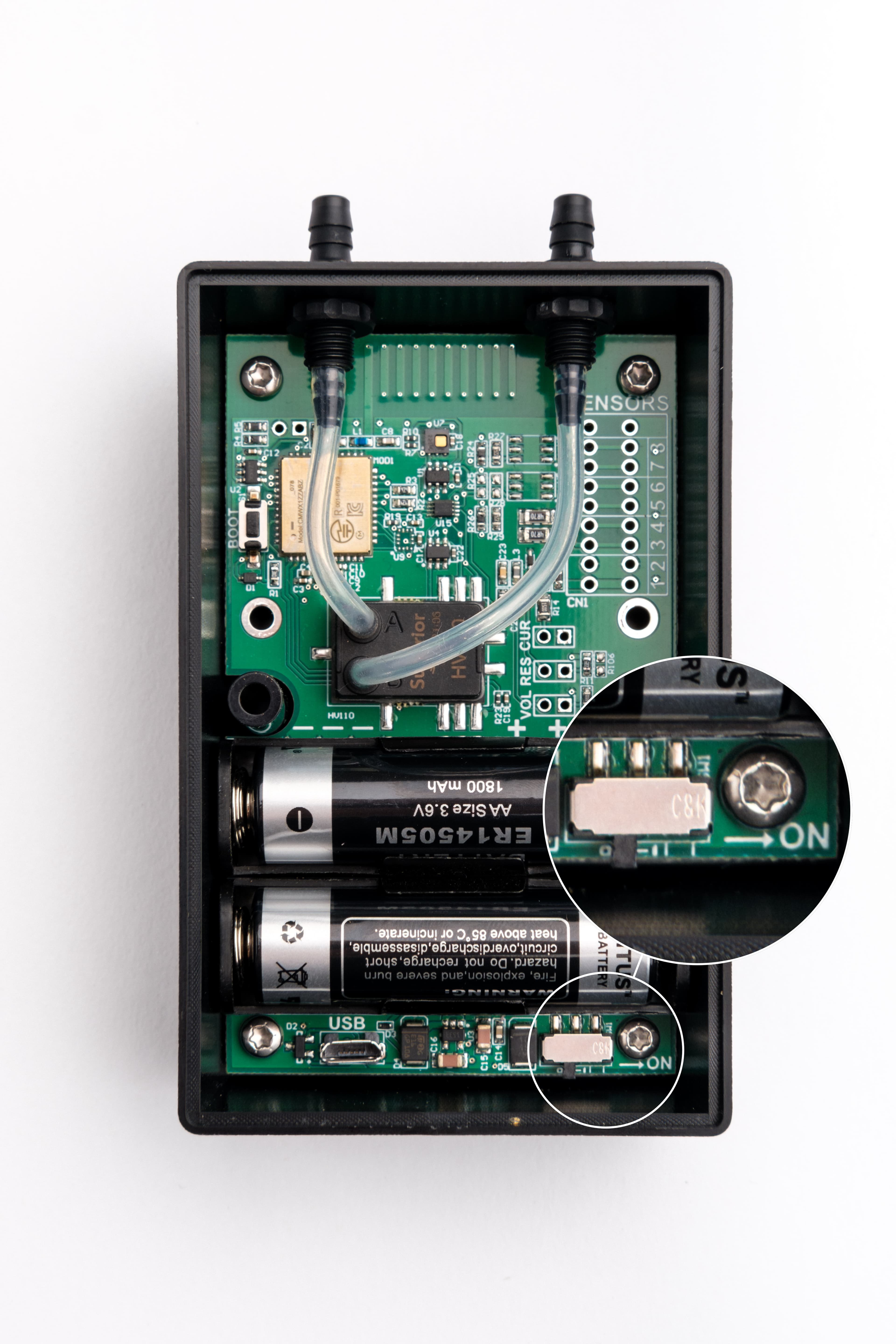
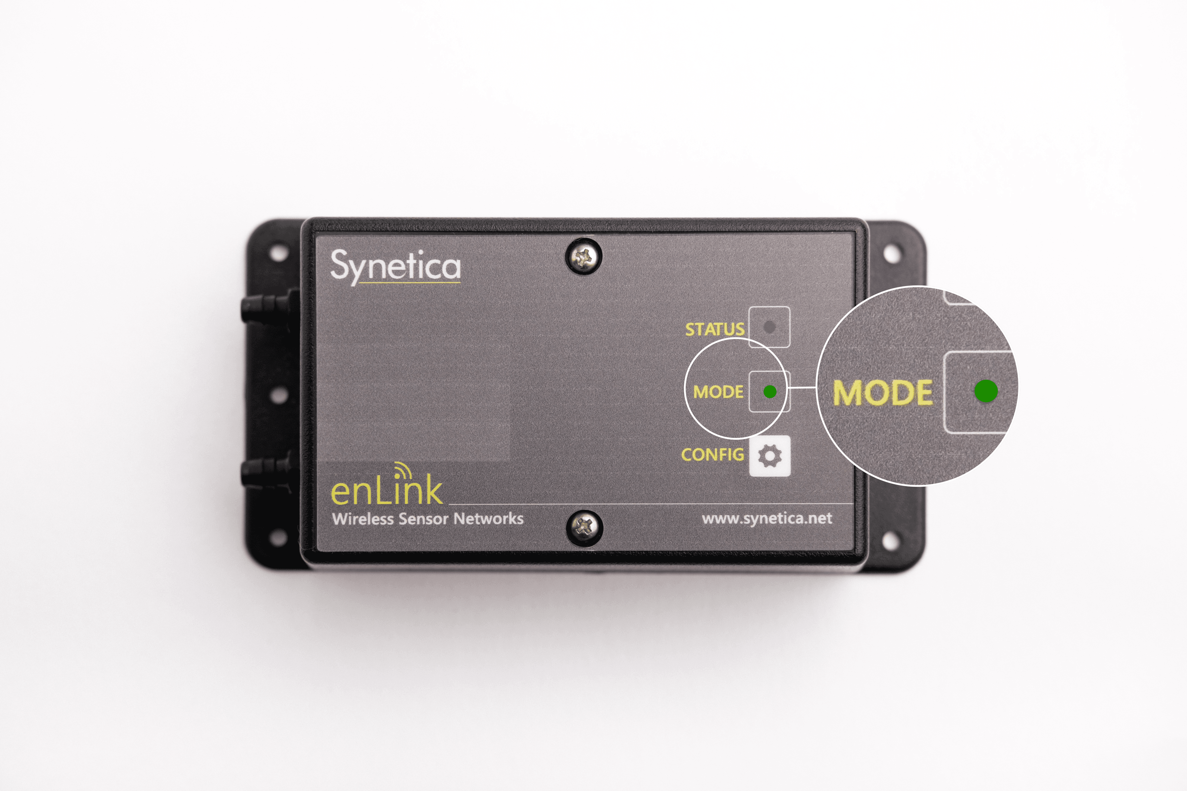
The Status will begin to flash red.
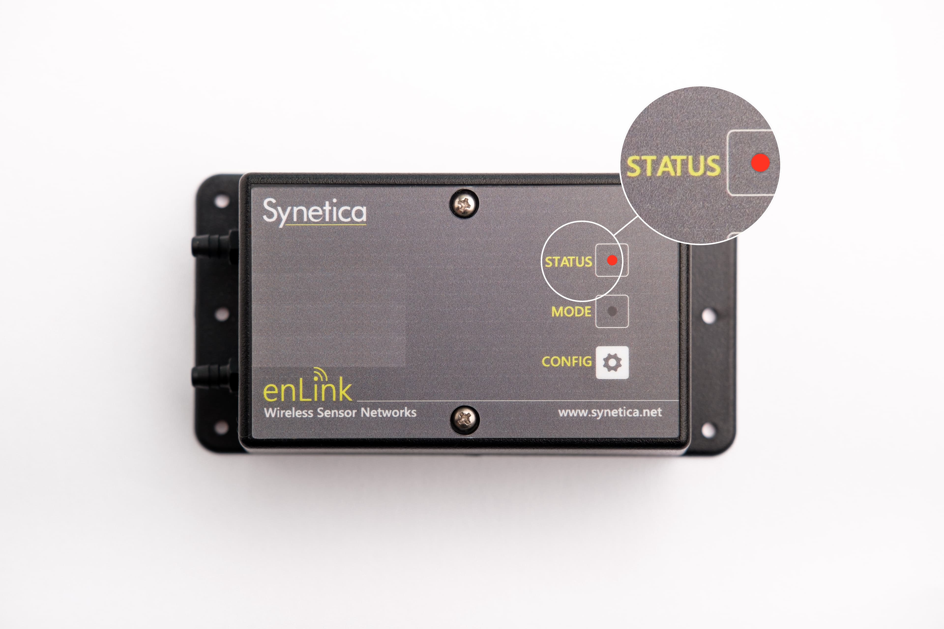
Place the cover back on the device.
Use a Phillips screwdriver to secure the two screws on the front of the device.
Once the device is connected to a gateway, the Mode should flash green five times.
Turn off
Use a Phillips screwdriver to remove the two screws on the front of the device.
Remove the cover.
Move the ON switch to the left.
Place the cover back on the device.
Use a Phillips screwdriver to secure the two screws on the front of the device.
Reset
Use a Phillips screwdriver to remove the two screws on the front of the device.
Remove the cover.
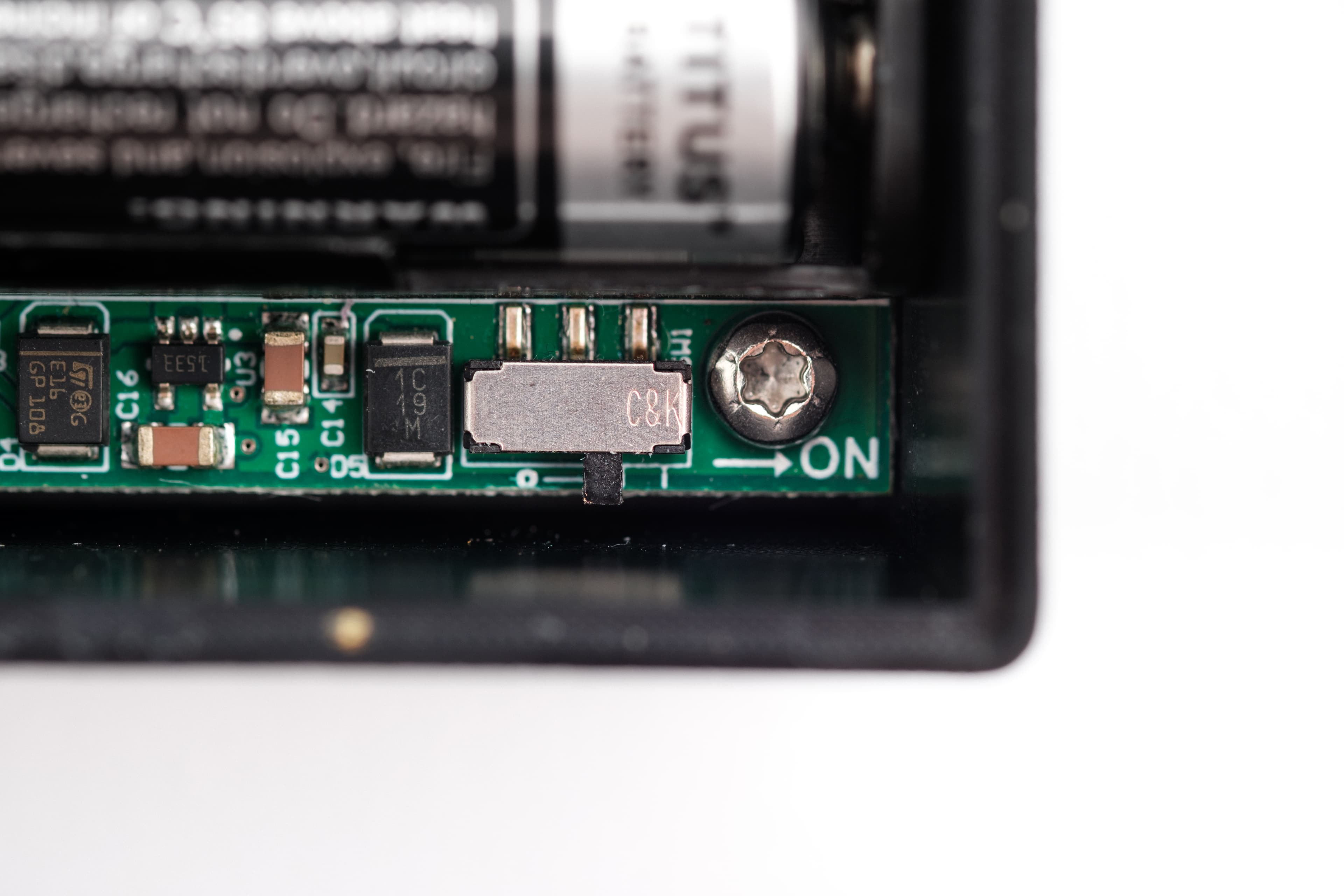
Move the ON switch to the left.

Move the ON switch to the right.
The Status will begin to flash red.

Place the cover back on the device.
Use a Phillips screwdriver to secure the two screws on the front of the device.
Once the device is connected to a gateway, the Mode should flash green five times.

Turn on
Using a Phillips screwdriver, remove the four screws on the back of the device.
Remove the back panel.
Insert the two batteries included in the package.
Place the cover at the back of the device.
Using a Phillips screwdriver, secure the four screws on the back of the device.
Turn off
Using a Phillips screwdriver, remove the four screws on the back of the device.
Remove the back panel.
Remove the two batteries.
Place the cover at the back of the device.
Using a Phillips screwdriver, secure the four screws on the back of the device.
Reset
Using a Phillips screwdriver, remove the four screws on the back of the device.
Remove the back panel.
Remove the two batteries.
Place the cover at the back of the device.
Using a Phillips screwdriver, secure the four screws on the back of the device.
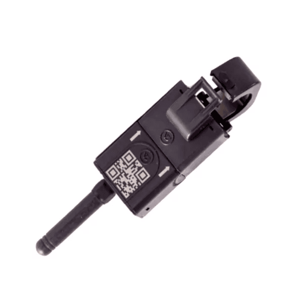
We recommend that this sensor is only installed by professionals with knowledge of electrical systems.
Turn on
Clip the sensor around an appropriate wire. This sensor draws its power from an active wire and requires no further action.
Turn off
Unclip the sensor from the installed wire and remove the device. The capacitor of this device will hold power after being disconnected and will drain over time. You do not need to take any further action.
Reset
Unclip the sensor from the installed wired and remove the device.
Clip the sensor around the appropriate wire.
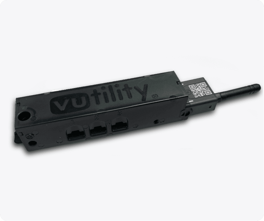
We recommend that this sensor is only installed by professionals with knowledge of electrical systems.
Turn on
Clip the sensor around an appropriate wire. This sensor draws its power from an active wire and requires no further action.
Turn off
Unclip the sensor from the installed wire and remove the device.
Reset
Unclip the sensor from the installed wired and remove the device.
Clip the sensor around the appropriate wire.
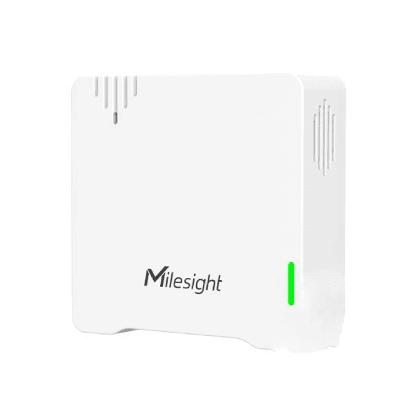
Turn on
Press and hold the power button on the back of the device for more than three seconds.
A green light should flash.
Turn off
Press and hold the power button on the back of the device for at least five seconds.
The green light should remain on while you are holding the button.
Reset
Press and hold the power button for 10 to 15 seconds.
A green light should flash briefly.
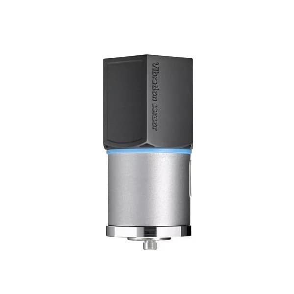
Turn on
Press and hold the power button for at least three seconds. You may use a pen or something similar to press the button firmly.
A green light should appear and start to flash as it searches for a gateway.
The light turns off when it has connected to a gateway successfully.
Turn off
Twist the top off the device.
Remove the battery by carefully sliding it out of the base.
Remove the wire with the white connector.
Reset
Twist the top off the device.
Remove the battery by carefully sliding it out of the base.
Remove and then reattach the wire with the white connector.
Slide the battery back into the base.
Use a screwdriver to fasten the screws on the top of the device.
Press and hold the power button for at least three seconds. You may use a pen or something similar to press the button firmly.
A green light should appear and start to flash as it searches for a gateway.
The light turns off when it has connected to a gateway successfully.
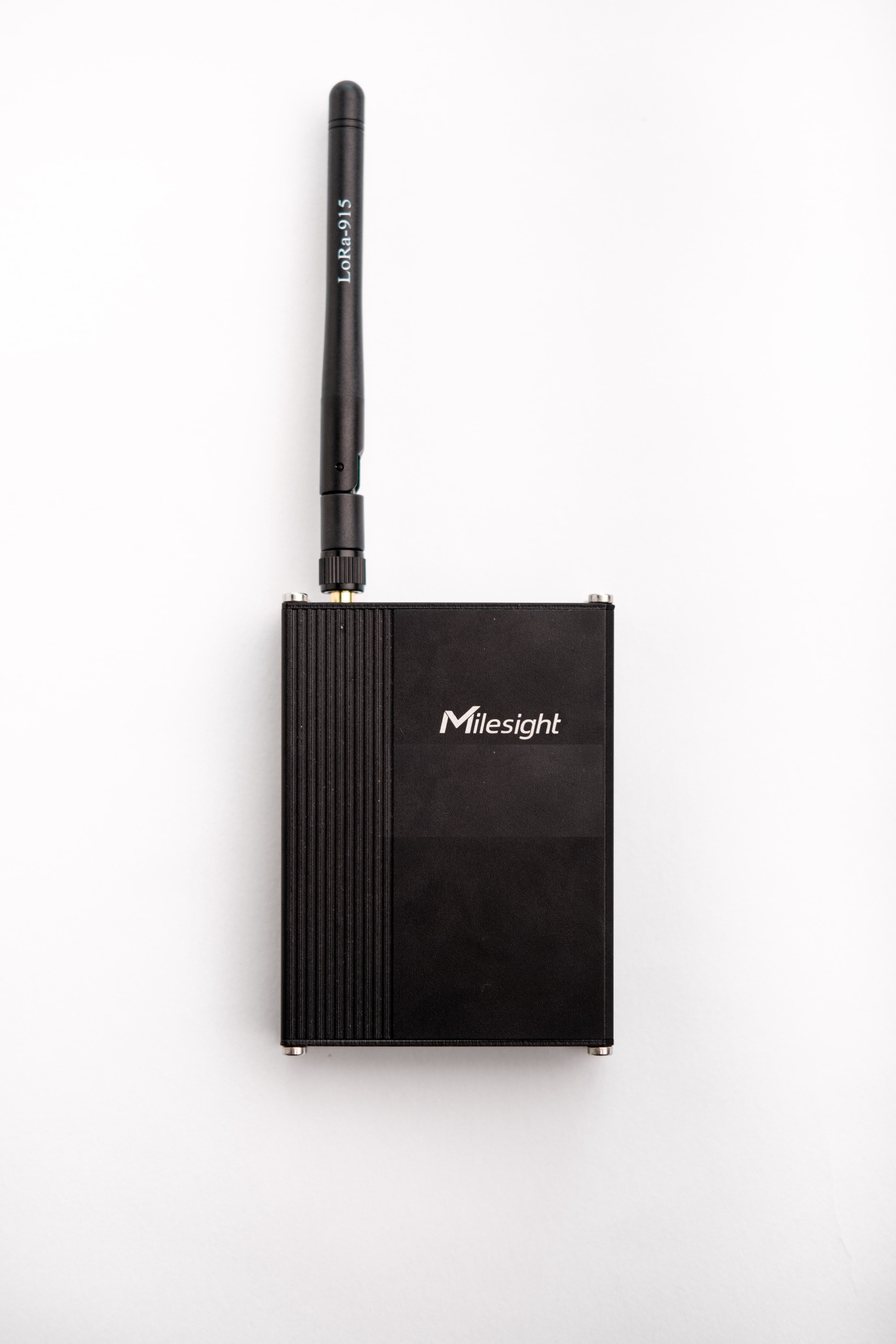
Turn on
Connect the sensor to the included power supply.
The System LED should appear static green.
Turn off
Remove the power supply.
Reset
Remove the power supply.
Reconnect the sensor to the included power supply.
The System LED should appear static green.
![]()
Turn on
Use a Phillips screwdriver to remove the screws on the rear cover.
Insert three AAA batteries.
The LED should flash and connect to a GPS. We recommend for you to be in an area with a good GPS reception, ideally outside if possible.
Turn off
Use a Phillips screwdriver to remove the screws on the rear cover.
Remove the batteries from the device.
Reset
Use a Phillips screwdriver to remove the screws on the rear cover.
Remove and then insert the batteries again.
The LED should flash and connect to a GPS. We recommend for you to be in an area with a good GPS reception, ideally outside if possible.
![]()
This sensor requires more detailed installation, please contact our Support team.
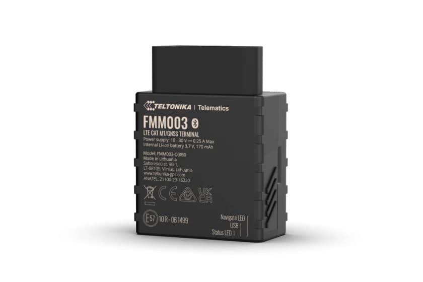
Turn on
Connect the device to an available OBDII socket in your vehicle.
Turn off
Remove the device from the OBDII socket in your vehicle.
Turn on
Press and hold the power button for more than three seconds.
The LED indicator turns on.
Turn off
Press and hold the power button for more than three seconds.
The LED indicator turns off.
Reset
Press and hold the power button for more than 10 seconds.
The LED indicator flashes briefly before it turns off completely.
Turn on
Press the ACT button for more than three seconds.
A green light should appear and start to flash as it searches for a gateway.
The light becomes static for five seconds when it has connected to a gateway successfully.
Turn off
Press the ACT button five times in quick succession.
A light should appear static red for five seconds.
Reset
Press the ACT button five times in quick succession.
A light should appear static red for five seconds.
Press the ACT button for more than three seconds.
A green light should appear and start to flash as it searches for a gateway.
The light becomes static for five seconds when it has connected to a gateway successfully.
We recommend having an interval of at least 10 seconds between turning the device on and off and vice-versa.
Turn on
Use a screwdriver to remove the screws on the cover.
Remove the cover.
Insert two AAA alkaline batteries.
Press any key until the green indicator flashes.
Turn off
Press the two function keys at the same time for five seconds.
The green light should flash.
Once you release the function keys, the green light should flash 20 times and then the device should turn off automatically.
Reset
Press the two function keys at the same time for five seconds.
The green light should flash.
Once you release the function keys, the green light should flash 20 times and then the device turns off automatically.
Wait for at least 10 seconds.
Press any key until the green indicator flashes.
Turn on, off, and reset gateways
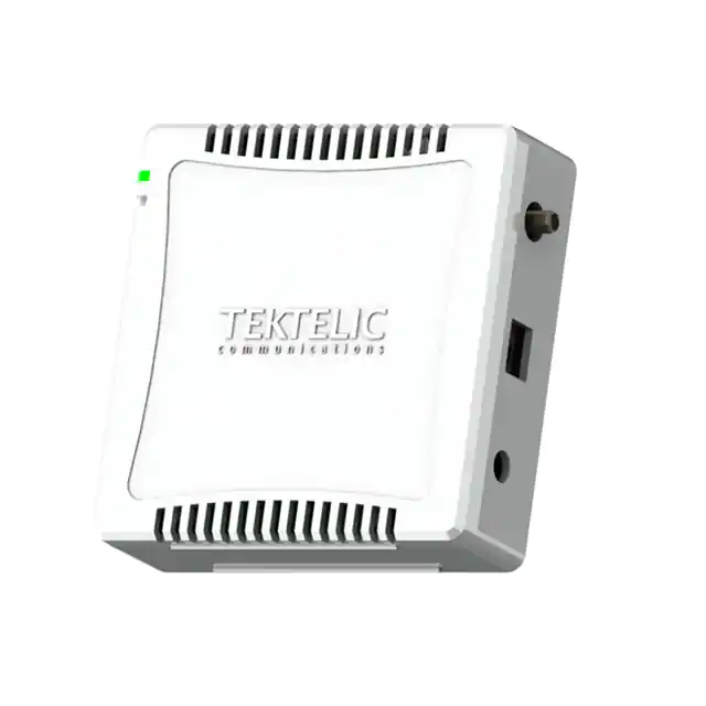
Please note that the LED indicator on the front of the device flashes green periodically and sometimes changes to solid green to indicate that the device is operating normally.
Turn on
Attach the antenna included in the package.
Connect the device to a power source.
Plug in the device.
Turn off
Unplug the device.
Remove the screws from the battery cover on the bottom of the device.
Remove the battery cover.
When you see a cable with a white connector, pull the connector to disconnect the battery backup.
Reconnect the battery backup.
Place the battery cover back on the bottom of the device.
Secure the screws on the battery cover.
Reset
Unplug the device.
Remove the screws from the battery cover on the bottom of the device.
Remove the battery cover.
When you see a cable with a white connector, pull the connector to disconnect the battery backup.
Wait for 20 seconds.
Reconnect the battery backup.
Place the battery cover back on the bottom of the device.
Secure the screws on the battery cover.
Plug in the device.
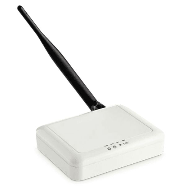
Turn on
Attach the antenna included in the package.
Connect the device to a power source.
Plug in the device to an ethernet outlet. Alternatively, you can review the guide to set up and connect gateways via Wi-Fi.
Plug the device into a power source.
Turn off
Disconnect the device from the power source.
Reset
Disconnect the device from the power source.
Disconnect the ethernet port if it is connected.
Wait for several seconds.
Reconnect the ethernet port.
Plug the device into a power source. The power indicator changes to green as the device powers up.
Additional information
The power indicator changes to green as the device powers up, but after a few seconds, it changes to red, and all other status indicators should be green. If the power indicator does not show this pattern at any point, review the following troubleshooting steps.
Power: This light should be red. If it is not, ensure that the power cable is connected properly and is plugged into a functioning power source. If the problem persists, try a different power source.
LoRa: This light should be green. If it is not, ensure that the antenna is attached properly.
WAN (Globe symbol): This light should be green. If not, ensure that the ethernet cable is connected properly to a port with connectivity. You may also need to add your ethernet to your allowlist.
Wi-Fi (Wi-Fi symbol): This light should be green. If it is not, review the guide to set up and connect gateways via Wi-Fi.
Frequently asked questions
The USB-C port on the Standard Temperature & Humidity Sensor is designed specifically for device setup and configuration, and not intended for charging. You can power the sensor using the designated batteries instead.
Was this page helpful?
Thank you for letting us know.